
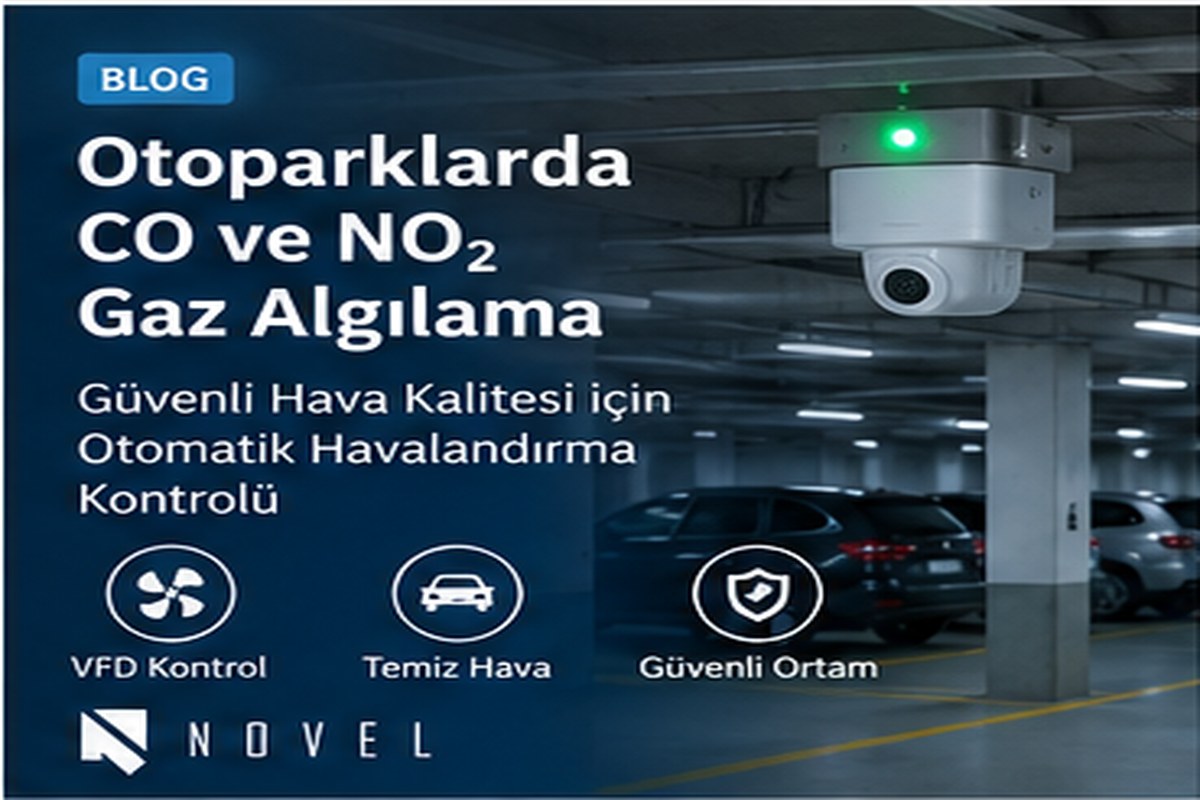
In enclosed car parks, gases originating from vehicle exhaust can accumulate in areas where ventilation is inadequate or airflow is poor. The source CETCI application note addresses continuous monitoring particularly for carbon monoxide (CO) and nitrogen dioxide (NO₂) which can originate from diesel vehicles, as well as modulating ventilation fans via variable frequency drives (VFD) based on gas levels.
Increasing and decreasing fan speeds based on gas concentration rather than running fans continuously at full speed provides a more controlled approach in terms of both safety and energy management.
Which Gases Are Monitored in Enclosed Car Parks and Why?
According to the source document, one of the most common exhaust pollutants in car parks is CO. In facilities where diesel engines are present, NO₂ risk must also be taken into account. The document also notes that hydrogen accumulation in electric vehicle charging areas, and flammable gases such as propane or methane under certain special site conditions, may also be considered in the evaluation.
Therefore, the design should not be treated merely as "installing CO sensors"; vehicle types, fuel diversity, floor geometry, ramps and entrances/exits, mechanical ventilation points, and stagnant air zones in the facility must all be evaluated together.
Why Is VFD Fan Control Used?
In the source system, the DCC controller can send a 4–20 mA analogue output to the VFD to modulate fan speed up and down according to gas levels. In this way, rather than operating fans continuously at full capacity, they can be brought into operation at higher speeds when the need arises.
The document particularly emphasizes that continuous operation of fans increases energy consumption and can adversely affect motor service life and maintenance requirements. The objective of the VFD-controlled approach is to reduce unnecessary fan operation while maintaining safe air quality.
The Most Critical Factor in Sensor Placement: Airflow
Sensor positioning is just as important as sensor technology. The source document recommends considering sensors in stagnant air zones and at points where representative air circulation exists, yet avoiding placing them directly within very high-velocity air streams. Car park entrances, lift lobbies, exhaust fans, and fresh air supply fans can influence measurements.
In its example application for commercial vehicle exhaust monitoring, the source indicates that one sensor can cover approximately 5,000–7,000 ft² (approximately 464–650 m²) area or approximately a 12–14 m radius . This value is not a project design criterion but a manufacturer application example; in an actual project, geometry and air movements must be evaluated separately.
Mounting Height and Control Panel
The typical mounting height recommended in the source document for the DCC is the range representing human breathing zones, 4–6 ft . The controller can be mounted on a column or wall. Two 5 A SPDT dry contact relays are provided on the DCC; the relays can be programmed for alarm functions such as fan control, time-delay operation, or remote strobe/horn activation.
Typical Sensor Configurations
| Configuration | Objective |
|---|---|
| Internal CO + internal NO₂ | Monitoring two gases on a single controller |
| Internal CO + remote LPT NO₂ | Relocating the NO₂ sensor to a more suitable remote point |
| Internal NO₂ + remote LPT CO | Positioning the CO sensor at a separate representative point |
| CO or NO₂ + remote combustible gas sensor | Evaluating additional risks such as H₂, propane, or CH₄ |
Design Checklist for Car Park Gas Detection Systems
- Identify vehicle and fuel types.
- Assess whether additional gas risks exist beyond CO and NO₂.
- Incorporate airflow, entrance/exit, fan, and ramp zones into the project design.
- Determine sensor quantities based on zoning and air movement, not merely m² calculations.
- Define alarm relays alongside fan, strobe/horn, and building automation scenarios.
- Clarify 4–20 mA signal scaling and fail-safe behaviour in VFD control during the project engineering phase.
Which CO / NO2 Gas Detector Should Be Selected for Car Parks?
NOVEL's CETCI LPT series product page features fixed transmitter options with CO and NO₂ sensors. In enclosed car park applications, multi-channel/digital architectures such as the LPT-P or analogue transmitters should be engineered according to area size, VFD fan control, BAS/BMS integration, and sensor count. Review Car Park Gas Detectors.
Let Us Select the Right Gas Detector for Your Application Together
Share your target gas, expected concentration, area layout, and automation requirements. The NOVEL Technical Team will conduct a technical assessment for sensor type, installation location, and system architecture.
Technical Support / Request a QuoteReview Car Park Gas Detectors
Frequently Asked Questions
Which gases should be measured in an enclosed car park?
In the source application note, CO and NO₂ are primarily addressed. Depending on the vehicle/fuel profile of the facility, additional gases such as hydrogen, propane, or methane can also be incorporated into the risk assessment.
Do car park fans have to run continuously?
In the source solution, VFD fans are intended to be modulated up and down via a 4–20 mA signal according to gas levels; this provides an alternative control approach to continuous full-speed operation.
How many square metres does one sensor cover?
The manufacturer application example specifies approximately 464–650 m² / a radius of 12–14 m. However, actual coverage depends on site conditions such as geometry, airflow, columns, and fan placement.
Where should the sensors be installed?
Preference should be given to locations capable of sampling representative air and covering dead air zones, whilst not being directly exposed to high-velocity airflow.
How does the DCC controller control the VFD fan?
According to the reference document, the DCC sends a 4–20 mA analogue signal to the VFD based on the gas level, thereby ramping the fan speed up or down.
What does NOVEL deliver in car park gas detection projects?
NOVEL can provide technical support for gas selection, sensor placement, control panel/automation architecture, product supply, and establishing the commissioning approach.
Reference and Technical Note
The application architecture and model-specific technical details in this article have been compiled from an application document provided by Critical Environment Technologies Canada Inc. . As source materials may be superseded, current product codes, certificates, measuring ranges, and local regulations must be independently verified prior to project design or procurement.
Author: NOVEL Technical Team
Publication date: 7 September 2026